 microServiceBus.com DOCS
Running microServiceBus-node on a yocto image
Intro
Yocto is an huge topic and to get you started we are going to setup an Raspberry Pi to run an custom pre built Yocto image. The pre built image contains 4 partitions with some key parts that enables microServiceBus.com to do remote firmware updates.

If you have previous experiences with Yocto and only looking to include the microServiceBus agent to your build have a look at meta-microservicebus-node
Partition 1 /boot
The boot partition contains the bootloader, in this case U-Boot. The bootloader is first to run after power up. U-Boot is responsible to load the Linux kernel into memory and decide if RootFS 1 or 2 should be mounted by the kernel.
Partition 2 and 3 /rootfs
In the rootfs partitions all Linux user space software is installed. There is two rootfs partitions to be able to update and swap firmware, only one is active at a time. The software most interesting for us is microServiceBus-node and RAUC. microServiceBus-node is responsible for installing and updateing microServiceBus-core. microServiceBus-core will check for new firmware, if newer firmware exists microServiceBus-core will download firmware and then call RAUC to install and swap rootfs next boot.
Partition 4 /data
Data partition is used to store data that will be persistent between firmware updates. microServiceBus-node runs by “msb” user whose home directory is located under /data/home/msb. The microServiceBus agent stores scripts and data under the home directory by default.
Yocto
The Yocto Project is an open source collaboration project that helps developers create custom Linux-based systems regardless of the hardware architecture.
Yocto build system runs on Linux but this tutorial will use pre build files and is targeted Windows as an host system. In this tutorial we will use target to reference the Raspberry Pi and host to reference the PC used to write the SD-card.
Tip! For more info regarding Yocto please visit Yocto project
RAUC
This image use RAUC software to apply firmware updates. microServiceBus-node will download new firmware from mSB.com and call RAUC install over d-bus to trigger the update. RAUC use X.509 cryptography to sign the update bundles, in this tutorial the example bundles is signed using an demo key.
Tip! For more info regarding RAUC please visit RAUC
Hardware
To follow along this tutorial you need some hardware.
Target
- Raspberry Pi 3 B/B+
- USB power supply
- Micro SD card with a capacity of at least 8 GB
- LAN, cable or WiFi
- HDMI cable and screen (Optional)
- USB keyboard (Optional)
- USB flash drive (Optional)
Host
- Windows PC, Linux or MAC should be fine but tutorial is targeted Windows
- Micro SD card reader
- Access to same LAN as target is connected to, cable or WiFi
1. Getting started
Here is some software that is good to download/install before moving on
- RPi3 SD-Image complete Yocto image for RPi3 SD-card
- RPi4 SD-Image complete Yocto image for RPi4 SD-card
- RPi 3 Firmware-bundle an bundled rootfs for remote update
- RPi 4 Firmware-bundle an bundled rootfs for remote update
- PuTTY will be used to connect to target and to generate ssh keys
- Etcher to write image to SD-card
2. SSH-Keys
The Raspberry Pi setup use SSH-keys for authorization when connection with SSH from host. If you already have an public and private key pair you can skip this section. To create an SSH-key pair follow the steps below.
- Start PuTTYgen( Start menu -> All Programs -> PuTTY-> PuTTYgen)
- Press “Generate” and start moving mouse to generate randomness, when complete the public key appears in the window
- Specify an pass phrase to protect the private key, this is optional
- Save private and public key, good to keep PuTTYgen open for copy/paste later.
Tip! If you have problem you can follow this guide
3. Write SD-Card
This will erase all content on the SD-Card, backup any data before continuing!
- Open Etcher and select image and drive and then flash!
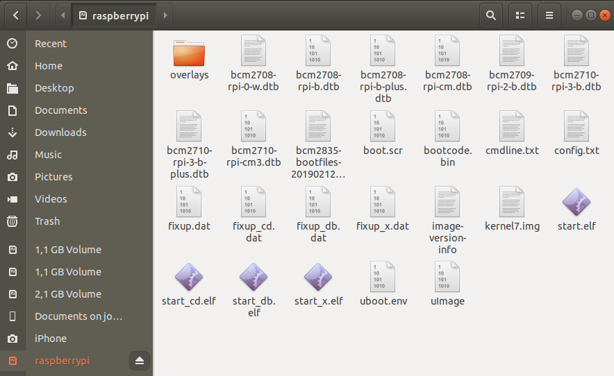
- After completion the boot partition should appear under Computer in the explorer, it may use raspberrypi as label.
4. SSH authorized_keys
To add your public SSH-key to the Raspberry Pi image you need to create an authorized_keys file. An init script will copy your key to the active rootfs on boot, you can use an USB flash drive or place the file on the boot partition on the SD-card.
- Open an text editor like Notpad++.
- Copy paste the public key from PuTTYgens key field, if you closed PuTTYgen you can open it and load your private key again
- If you use Notpad++ change end of line (EOL) to Unix, go to Edit->EOL Conversion->Unix (LF)
- Save file to the boot partition or USB flash drive as “authorized_keys”(no file ending)
Your file should look something like below:
ssh-rsa AAAAB3NzaC1yc2EAAAABJQAAAQB6tFAQLjZyldp187xJ4WANAikn6kf5o1u8HQBB1TpJFYfFhCNskX9oT1XC6rfD5Ar817p329vjppzY4kNOjIEIYIOLy8dWGcGGNEDjB9G+pczLp3J8cAWEic+bpB9mI6HGQwABb6AOIwuTw91INJwt7++4S6I9xbtECCTGWyb70pLWstqwlN8GXovLe/+vkMHI5PSJeQJLfabTk/SjM4gbD9GemHBcLbbCnpmXQYbG5jLPpF7Hhc8Gc7/NrzB7GwZ55HPkcz/oISVuCWReKGpSWIJno72FvpF4OeIyc/bLiw5H8VReyT9A9W3RUNQOmTuVfkBcIQZ4tdocBc0PxTkB rsa-key-20190603
5. WiFi config
If you use cable to connect to LAN you can skip this section. As the Raspberry Pi is intended to run headless(no display) and be able to swap rootfs without losing your WiFi settings an configuration file can be copied to the boot partition. An init script will copy your configuration file to the active rootfs on boot, you can use an USB flash drive or place the file on the boot partition on the SD-card. WPA-Supplicant is used to setup WiFi on the Raspberry Pi.
WPA-Supplicant template for WPA and WPA2:
ctrl_interface=/var/run/wpa_supplicant
ctrl_interface_group=0
update_config=1
country=SE

network={
        ssid="RPI_WIFI_SSID"
        scan_ssid=1
        psk="RPI_WIFI_PSK"
}
- Open an text editor like Notpad++ copy paste the above template
- Edit country code to match you location, this is so that the 5G networking can choose the correct frequency bands.
- Edit ssid and psk to match your WiFi SSID and password
- If you use Notpad++ change end of line (EOL) to Unix, go to Edit->EOL Conversion->Unix (LF)
- Save the file to the boot partition or USB flash drive named “wpa_supplicant-wlan0.conf”
Tip! For more info regarding WPA-Supplicant conf you can read here
6. microServiceBus-node service config
To start microServicebus-node on the Raspberry Pi an service file is used to auto start it and restart it in case of failure. There is an default service file on the SD-image already but you can add an custom service file to the boot partition to set different configurations for microServiceBus. We are going to use this to set sign in name and verification code. The default service file use white list and MAC address for sign in. An init script will copy your service file to the active rootfs on boot, you can use an USB flash drive or place the file on the boot partition on the SD-card.
microServiceBus-node service template:
[Unit]
Description=MicroServiceBus as a Service

[Service]
ExecStart=/usr/bin/node /usr/lib/node/microservicebus-node/start.js -c [YOUR CODE] -n  [YOUR NODE NAME]
WorkingDirectory=/usr/lib/node/microservicebus-node
Restart=always
StandardOutput=syslog
StandardError=syslog
SyslogIdentifier=nodejs
User=msb
Group=msb
Environment=PATH=/usr/bin:/usr/local/bin:/bin/:/usr/local/sbin:/usr/sbin:/sbin
Environment=NODE_ENV=production
Environment=MSB_PLATFORM=YOCTO
Environment=MSB_HOST=microservicebus.com
Environment=DAM_SOCKETPATH=/var/run/dam

[Install]
WantedBy=multi-user.target
- Open an text editor like Notpad++ copy paste the above template
- Change [YOUR CODE] and [YOUR NODE NAME] to match name and code on msb.com/Nodes
- If you use Notpad++ change end of line (EOL) to Unix, go to Edit->EOL Conversion->Unix (LF)
- Save the file to the boot partition or USB flash drive named “microservicebus-node.service”
- Unmount you SD-Card
7. Bootup
At this stage you hopefully have an working SD-Card to use in your Raspberry Pi. If you like to see the boot process connect an HDMI display to your Raspberry Pi and an keyboard to be able to interact. But if all off the above configuration is correct your Raspberry Pi node should come online in mSB.com if it have internet access.
- Insert SD-Card in Raspberry Pi
- If you used USB flash deviec for your configuration files insert the USB device
- Power on your Raspberry Pi
- Go to mSB.com/Nodes and check if your device is online, the first time this can take a while because mSB-core needs to be downloaded and installed. If your node is online congratulations, if not go to next section to be able to debug your node
8. Connecting using SSH
An SSH-server is running on the Raspberry Pi by default and allow connections using SSH-key authentication. If your configuration above is correct the generated public SSH-key have been added to ~/.ssh/authorized_keys and will grant you access.
- To connect with SSH you need the IP address of your Raspberry Pi, here is some tips on ways to get them.
- If you have access to the network router it is convenient to login and look at DHCP lease.
- Scan your network using an IP-scanner like nmap or Angry IP Scanner, it may show up with host name “raspberrypi3”. If you cant sort out witch device is your node it is good to scan before and after you connect you Rasperry Pi to the network. Warning on corporate LAN there may be very many devices connected to you network and running network scans can be violating your IT policy.
- If your node is online in mSB.com/Nodes you can get the IP address of the interface by going to Actions->Properties->Environment and unfold “networks”
{ "networks": [ { "name": "eth0", "ip_address": "192.168.0.100", "netmask": "255.255.255.0" }, { "name": "wlan0", "ip_address": "192.168.1.100", "netmask": "255.255.255.0" } ], "...": { }, "raucState": { } } - If you have an display connected to HDMI the IP address of the Ethernet and WiFi interface will be presented above login prompt like below:
 Poky (Yocto Project Reference Distro) 2.6.2 raspberrypi tty1

  eth0  192.168.0.100
 wlan0  192.168.1.100

 login:
If the address is empty the node may have been assigned an IP late or after fully booted, press enter to reprint the prompt. Default there is no root password, thus login local with keyboard is not possible. You need to authenticate with SSH-Key.
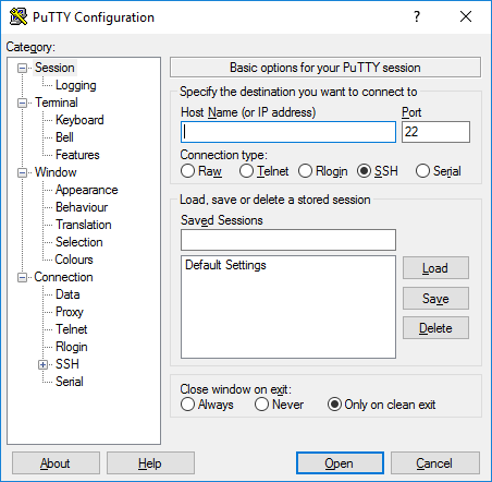
- When you have successfully located the IP address open PuTTY
-
Enter the Raspberry Pi address
-
Now we have to select our private SSH-key, in the tree to the left open Connection->SSH->Auth, then browse your private key.
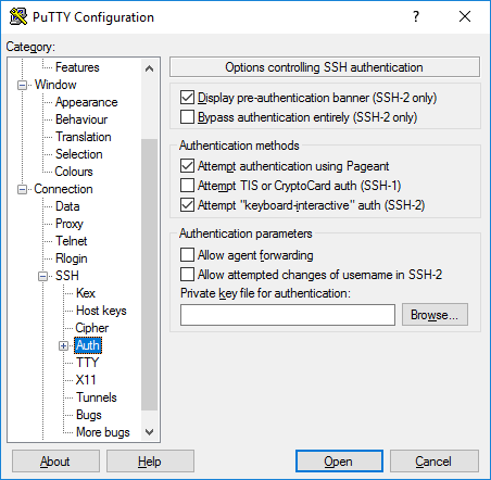
- Press open to start SSH session, if prompt for user name enter root
- You should now have access to an remote shell on the Raspberry Pi, you can set an root password if you like to be able to use the “HDMI” shell and keyboard.
 root@raspberrypi3:~# passwd
 Changing password for root.
Note, this password will not be permanent when you do firmware update later.
Tip! If you have problem this guide may help
9. Firmware update
When using Yocto and RAUC microServiceBus enable the possibility to do remote firmware updates. In this setup we will only update the rootfs but RAUC have the possibility to update kernel, data partitions or even the bootloader it the target hardware have support for it. Follow the steps bellow to upload and apply an new firmware to your target.
- If you haven’t download the example bundle above do it now, firmware-bundle
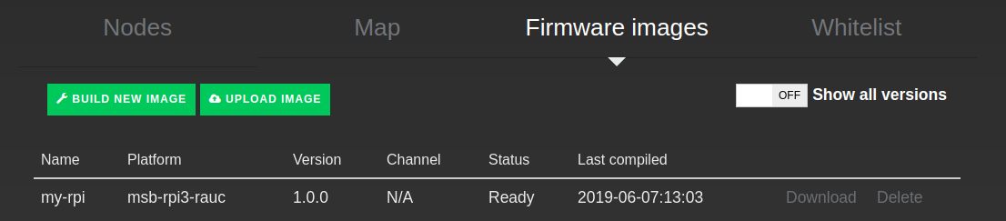
- Go to mSB.com/Nodes->Firmware images and press upload image.
- Fill in the image information, platform and version is the critical part. Platform is used by RAUC to determent if the firmware is applicable to the target and must therefore be exactly “msb-rpi3-rauc”. Version is used by mSB-core and mSB.com to determent if the target is running the latest version, this version should match the version of the bundle, in this case “1.0.0”
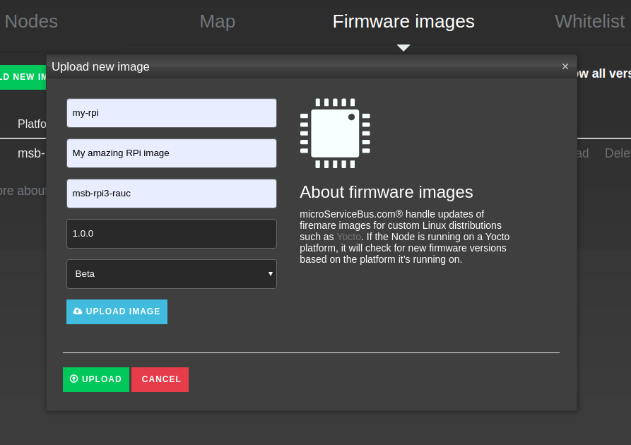
- Press the blue upload image button and select the firmware bundle
- Then press the green upload button to start uploading the image to mSB.com
- When finished you can navigate back to mSB.com/Nodes->Firmware images and verify that you bundle successfully was uploaded
- To be able to see the update process on the node you can run the command below in the shell
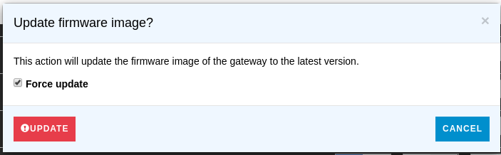
journalctl -u microservicebus-node -n50 -f - Trigger an firmware update by pressing Action->More options->Update firmware on the node in mSB.com/Nodes. Now the following processes will run on your node:
- mSB-core will download firmware image
- mSB-core will call RAUC to install and verify firmware
- mSB-core will reboot the node when RAUC signals completed, this will close your SSH connection
- After reboot U-Boot will boot to the new slot
- The init script will copy all custom configuration files from boot partition in to the new rootfs
- microServiceBus-node will start downloading and install mSB-core, this can take a while
- When mSB-core is installed the node will fetch and start all active flows defined in mSB.com/Flows for your node
- Done!
- When the firmware update is done go to mSB.com/Nodes, open Actions->Properties->Environment and unfold “raucState” here you can see the properties for all RAUC slots (rootfs0/1)
 {
 "networks": [ ],
   "...": { },
   "raucState": {
     "rootfs0": { },
     "rootfs1": {
       "installed.count": 24,
       "status": "ok",
       "type": "ext4",
       "sha256": "c83d89b7688cfd2a30a0bc0313a8e8223caee4740906cd25807974bf4bfed6f0",
       "bundle.compatible": "msb-rpi3-rauc",
       "device": "/dev/mmcblkp3",
       "boot-status": "good",
       "size": 115040256,
       "bundle.build": "20190528035741",
       "activated.timestamp": "2019-05-29T09:04:40Z",
       "installed.timestamp": "2019-05-29T09:04:35Z",
       "state": "booted",
       "bootname": "system1",
       "class": "rootfs",
       "bundle.version": "1.0.0",
       "bundle.description": "",
       "description": "",
       "activated.count": 25
     }
   }
 }
In rootfs0 you should see “state”: “inactive” and in rootfs1 “state”: “booted, this indicates that your node now have booted to your new firmware on rootfs1
- This information is accessible on the node by running the following command on the shell
rauc status --detailed - You have now completed an firmware update, if you get an new bundle the procedure is the same. The firmware version needs to be updated to indicate for mSB-core and mSB.com that there is an newer version. If you like to trigger an firmware update with the same version you can force an update by checking “Force update” when you trigger the update.
Back to home page: Home
Related content:
- Home
- Common Linux terminal commands
- Get insight using tracking
- Import nodes from CSV files
- Installing microServiceBus-node
- Working with meter configuration
- Migration information
- Node installation scripts
- Work with Node VPN interface and peers
- Reviewing the Audit log
- Roles, privilages and auditing
- Running microServiceBus-node on a yocto image
- Developing JavaScript Services in microServiceBus.com
- Developing Python Services in microServiceBus.com
- Site verification
- Using the Node terminal
- Using the Console
- Default keyboard shortcuts
- Working with service properties
Report bugs, broken links or missing images.. Create Issue